Programming
Bendex Office and CellControl Software
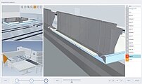
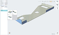
The Bendex Office software automatically programs the bending sequences based on the imported CAD data of the part:
- Import of STEP, DXF or GEO files
- Adding of angle corrections via material tables
- Automatic one-click programming of the bending sequences including the tool setup
- Ranking of bending strategies
- Simulation of the bending sequence in 3D
- Storage of the part program in a profile archive
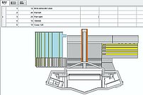
For special bending sequences, the CellControl Office software allows manual intervention in the automatically generated bending sequences
- Graphics-supported, manual modification of bending programs in the office
- Screens and menus identical with RAS CellControl machine
- Additional licenses are available for networks and multiple PCs
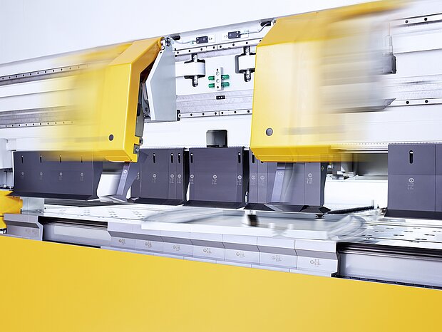
Automatic tool setup
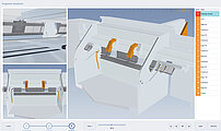
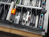
- The tool changer positions the upper beam tool segments automatically and quickly.
- The individually acting tool change grippers move toward each other with lighting speed, grab the upper beam tool segments and place them exactly in position.
- Tool changing within the program sequence is also possible, for example if the long sides of the part need to be bent before the short sides.
- The tool changer is self intelligent. The software recognizes the required tool length from the workpiece dimensions. It selects the appropriate tool segments and automatically calculates the fastest tool change strategy.
- In the bending program, it is also possible setting a fixed tool setup. This allows for example, to place specific tools with cut-outs on top of embossings in the blank.
- A magazine to the right and left of the upper beam stores tools that are currently not used.
Blank loading
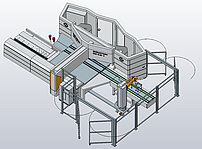
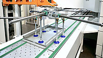
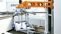
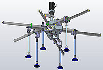
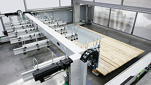
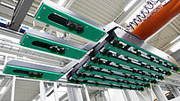
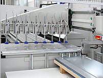
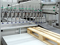
Gantry loader: Suction cup frame
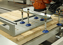
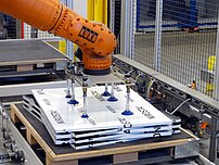
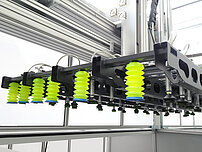
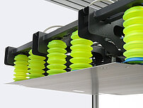
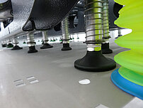
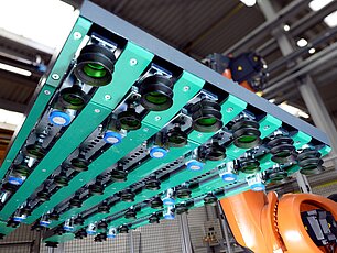
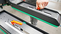
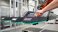
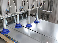
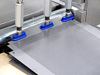
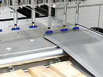
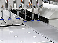
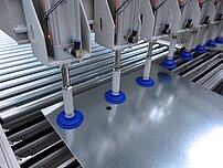
The suction frame is equipped with different size suction cups. A quick locking mechanism allows fast setups for maximum flexibility, if the suction cups need to be repositioned.
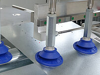
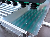
Peeling suction cups with a large stroke height can separate the top blank of a stack and ensure a smooth production process. A double material detection system makes sure that the suction frame has picked just a single blank. A clever software feature ensures that blanks with different dimensions, geometries and holes will be reliably loaded.
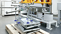
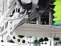
The spring mounted suction cups can lift blanks from a stack on an uneven floor. Moreover, even blanks with slight embossings, lying on a warped pile can be loaded.
Gantry loader with SheetFlipper
With the SheetFlipper, blanks lying on a stack of sheets can be loaded to the Multibend Center panel bender either flipped or not flipped over. The suction frame of the SheetFlipper picks up a blank, flips it over and transfers it to the suction frame of the gantry loader. The SheetFlipper can be added to the single station or the 2 station gantry loader.
- Optionally flipping or not flipping of blanks to be loaded
- Peeling suction cups separate the blank from the stack
- Two suction circuits for economical compressed air consumption
- Transfer of the flipped blank to the gantry loader
- Fast cycle times
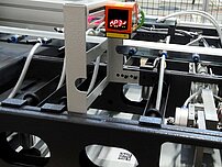
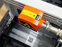
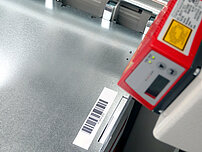
QR Code Scanner in gantry loader suction frame
A QR code scanner can be added to the 1 or 2 station gantry loader. The suction frame starts to the indicated stack of blanks. Each blank comes with a QR code. The scanner reads the QR code and loads the stored program. Thereafter, the suction frame lifts the top blank from the stack, check on double sheet and moves the workpiece to the Multibend Center.
Robotic blank loading with suction cups and magnets
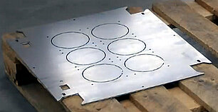
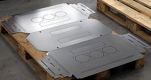
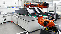
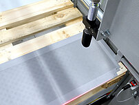
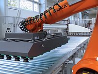
The intelligent load robot can loads blanks with a closed base surface using its standard suction frame. If blanks come with many holes or cut-outs the suction frame cannot create a vacuum. In this case, additional magnets can be integrated into the vacuum frame. This allows automatic loading of a significantly increased number of blanks by the robot.
- Loading blanks with multiple holes and cutouts
- Significant increase of blanks that can be loaded automatically
Flexible frame extension on the loading robot
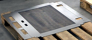
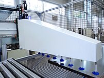
For blanks with large window cutouts or perforated middle sections, the standard suction frame of the intelligent loading robot on the RAS Multibend Center can not generate any vacuum to lift and load the workpieces. The suction frame with flexible suction frame extensions solves this aspect. The three extension arms with two suction cups each, can be manually setup so that even blanks with only a small frame can be automatically fed to the panel bender.
- Loading of blanks with only a small solid frame area
- Manually adjustable extension arms
MiniFeeder: Loading of different blanks from a single stack
- Example: Kit production of elevator panels
- Blanks for 10 elevators with 9 panels each
- Scanner reads barcode label attached to each blank and loads program
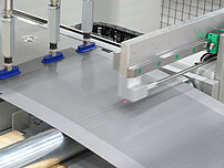
- MiniFeeder with 8 round suction cups
- Blank width sets number of active suction cups
- Material thickness check
- MiniFeeder transports blank to suction cup measuring table
MiniFeeder connection with robotic loading
In this blank loading option the MiniFeeder moves the blank from a punching machine via a roller table to the intelligent RAS blank loading robot. The robot picks the blank, flips it over and feeds it to the Multibend Center, without having to be programmed or taught. System requirements:
- Direct connection only
- Punching: One raw blank becomes one punched part
- The punching machine communicates the program name
- The Multibend Center loads the program and reognized the blank width out of the program
- The MiniFeeder activates the matching number of suction cups and pulls the blank onto the roller table
- The roller table transports the blank towards the Multibend Center and references it
- The intelligent loading robot flips the blank and feeds it into the Multibend Center
Bending
Folding beam with crowning option
The standard folding beam stands out with excellent bending results. This is based on the very rigid box design, which is provided with a basic crowning. This solution is completely sufficient for more than 95% of the applications in hundreds of installations so far. In order to meet even extreme requirements for straightness of bends and for step bending of radii, a folding beam with manual crowning option is available.
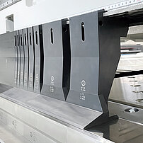
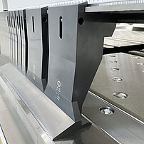
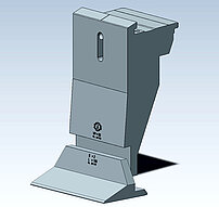
Divided two-piece upper beam tools
The upper beam tools of the RAS Multibend-Center panel benders offer large free spaces in front of and behind the tools. The clearance provides an almost infinite variety of design options for the parts. In addition to single-piece tools, divided two-piece tools are also available. What are the benefits of the divided two-piece upper beam tools?
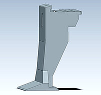
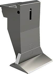
- The two-part tools allow the foot to be exchanged if individual parts require cutouts at the tool sole
- In the event of damage to the bending edge, only the lower foot needs to be replaced.
- It may also be necessary to change the foot when bending thicker materials that require reinforced tools
- If a low angle foot is advantageous for pre-bending closed profiles, only the foot needs to be changed
Unloading of finished parts
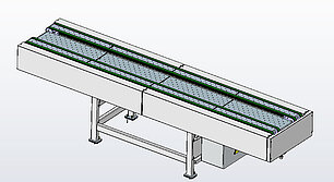
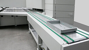
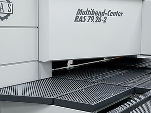
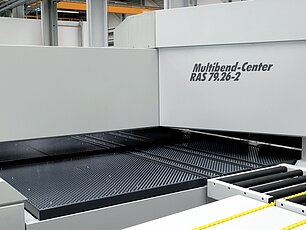
Finished part belt conveyor
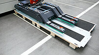
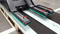
On the finished part belt conveyor, the 4 conveyor belts are exactly synchronized with the run-out speed of the finished parts from the Multibend Center.
- Gentle and smooth transport of bent parts
- Precise stopping and positioning of parts
- Lifting function of the belts for parts with negative last flange
- Manual unloading from the finished part belt conveyor
- Optional unloading automation with Palletizer or unloading robot
Palletizer unloading system
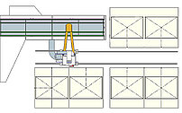
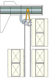
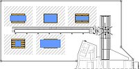
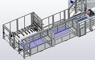
The Palletizer automates unloading and stacking of bent parts. In the stationary solution, the Palletizer stacks the parts on a single pallet. Alternatively, the Palletizer moves on a linear axis and can serve multiple stacking positions.
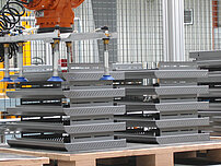
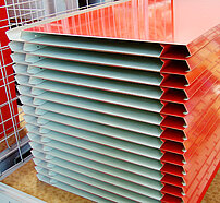
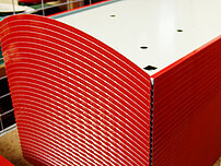
- Horizontal stacking of bent parts
- Manual part unloading still possible
- Number of stacking positions depend on the part size
- Stacking positions longitudinal or transverse to run-out
- Stacking directly on each other or with rotational offset
- Fixed or adjustable motorized suction frame
- Safety system with electrically monitored doors
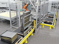
Pallet system with intelligent robot unloading
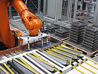
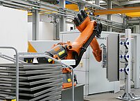
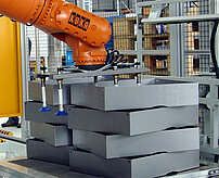
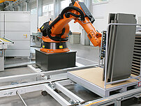
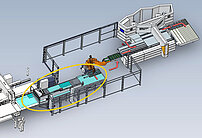
With automatic unloading and stacking of bent parts, the panel bender can be run in an unmanned shift. The unloading robot picks up the finished parts from the runout table and stacks them according to the selected stacking pattern. The intelligent unloading robot does not have to be taught or programmed.
- The pallet system automatically provides empty pallets
- Full pallets will be delivered to the forklift pickup position
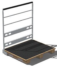
- Pallets without a back panel allow horizontal part stacking
- Pallets with a back panel also allow vertical stacking
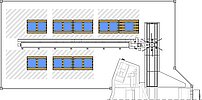
- The pallet system layout can be adjusted to local floorspace conditions
Intelligent unloading robot: Stacking strategies
There is no need to teach or program the intelligent unloading robot. Simply select a stacking strategy and the robot does the rest. Stacking strategy examples:
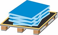
• Parts stacked horizontally
• Parts stacked horizontally and rotated to each other
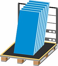
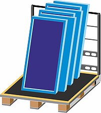
• Parts stacked vertically (pallet with back panel)
• Every second part turned
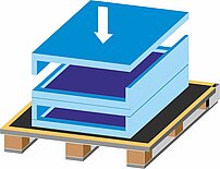
• Parts lying in each other
• Two stack side by side or behind each other


![[Translate to English:] Standard-Spannfuß des Hauptmanipulators](/fileadmin/_processed_/5/a/csm_Standard_HM_Fuss_3f5ace860e.jpg)
